
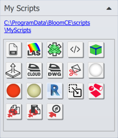
Access your local script objects with a single click from the custom icon.
Working with custom scripts
Local scripts are placed in
C:\ProgramData\BloomCE\scripts\MyScripts folder
Several utility tools are provided as detailed below
|
|

|
Opens a List Index of BIM categories in the model.
|

|
Process selected LAS pointcloud that does not have color, or is almost black.
|

|
Clash detection between two or more pointclouds
|

|
Extrude selected lines in Z direction
|

|
Select points on the edges of pointcloud. Edge Toplogy wiil create a line to represent edge and a point to represent a corner. Or, start by selecting a set of planes and then run the script to create lines and points at the intersection of two or more planes.
|

|
Flatten-DWG: Imported drawings from AutoCAD often have mulitple Z depth values. Use this script to move all drawing elements to a common XY plane.
|

|
Flatten-CLOUD: A two dimensional point cloud is created by reducing the z values of all points to the xy plane. The Model View may be used to further define the 2d point cloud. Use this script when you want an scale underlay as-built view in Revit or AutCAD.
|

|
Cut selected Polymesh object using the current model-view.
|

|
Export selected pointcloud objects to RCS format, when the RCS file is targetted to be imported into Autodesk Autocad.
|

|
Export selected pointcloud objects to RCS format, when the RCS file is targetted to be imported into Autodesk Revit.
|

|
Copy the Transforms of the selected object to the clipboard.
|

|
Paste the Transforms from the clipboard to the selected object.
|

|
Move the selected objects to the Revit coordinate system.
|

|
Select shapes (plane, cylinder or sphere) or CAD geometry to select overlapping points in a pointcloud. By default, points within 1 inch are selected, but repeatedly clicking raises the selection tolerance up to 5 inches.
|

|
Section offset
. This tool detects offset between CAD data and pointcloud geometry. When the two are quite close to each other, then usually Clash Detection or Deviation tools are used. But often the CAD geometry is quite off from the pointcloud, then deviation tools are not able to find the correspondence. The section offset tool cuts a section through both pointcloud and CAD geometry, then moves the CAD section in XY plane so that it best matches the pointcloud. Then it reports the translation offset.
|
|
|
|
|
|
|
Created with the Standard Edition of HelpNDoc: Free EPub producer